
Product details
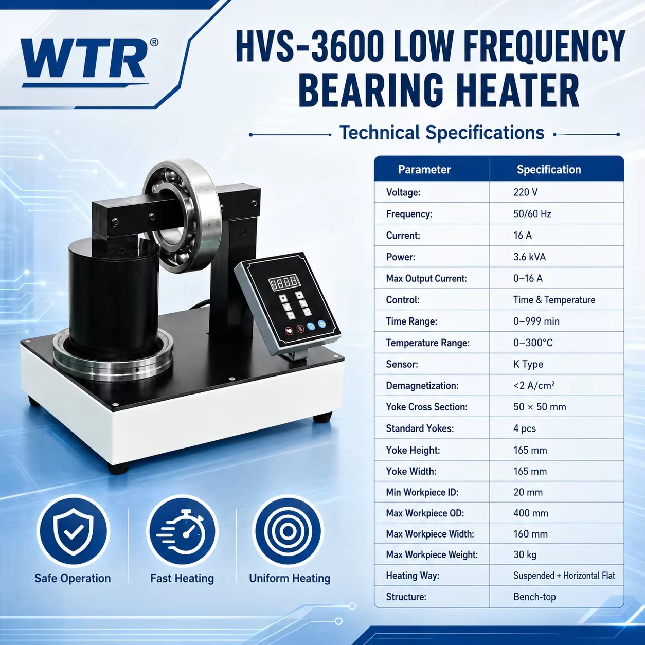
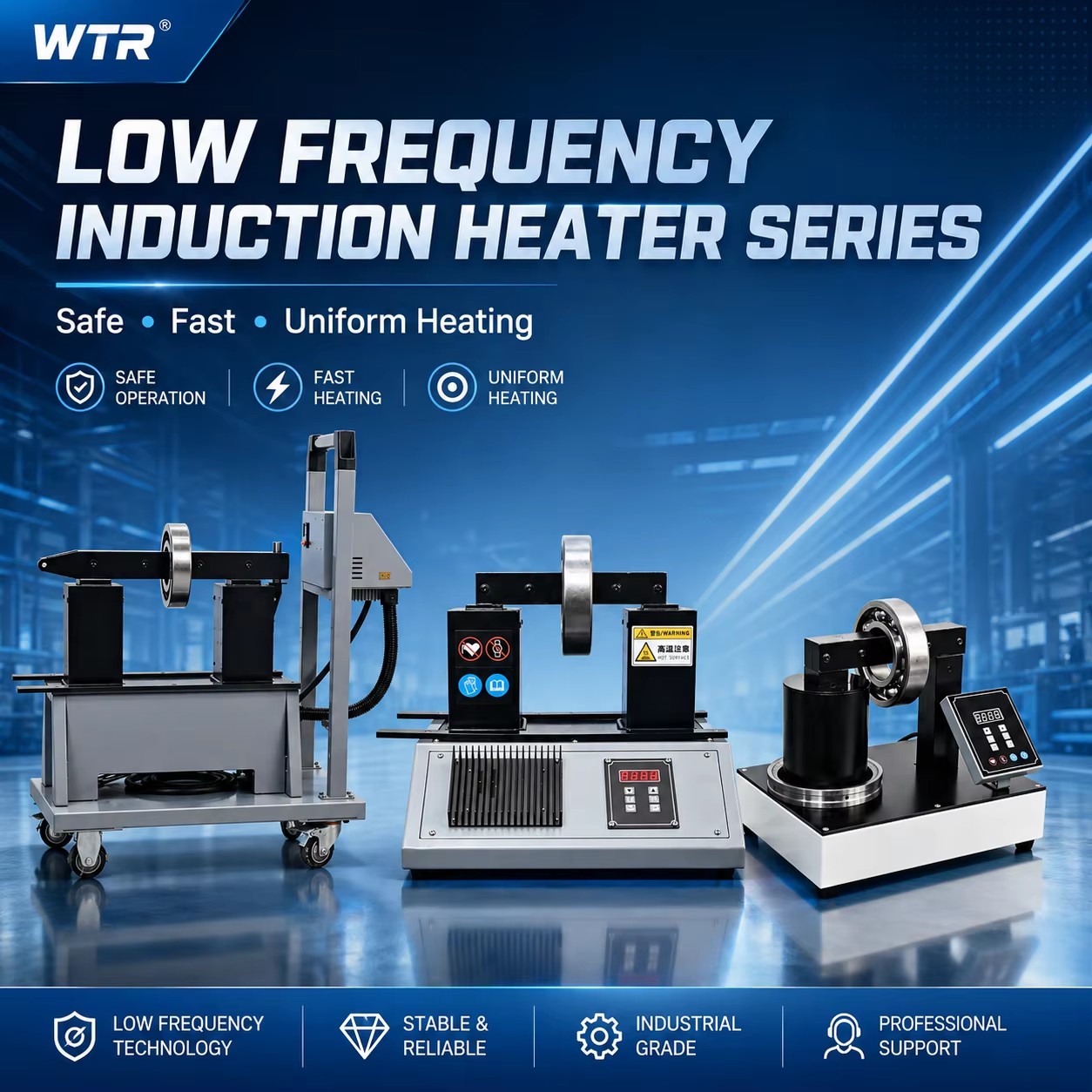
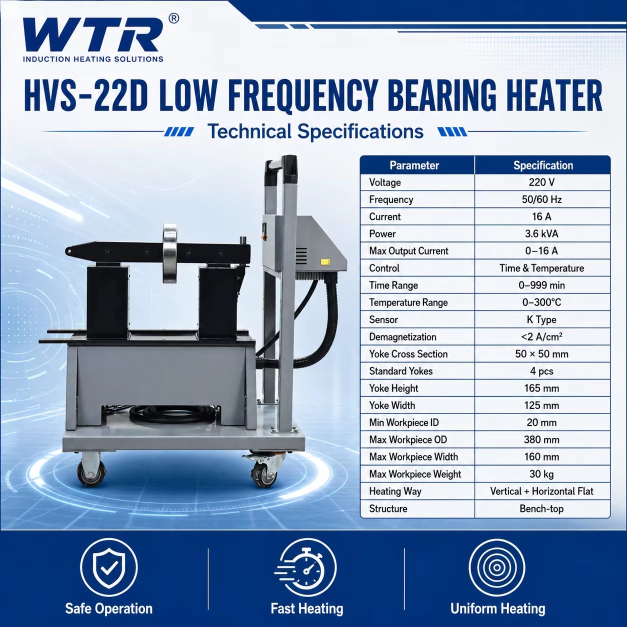
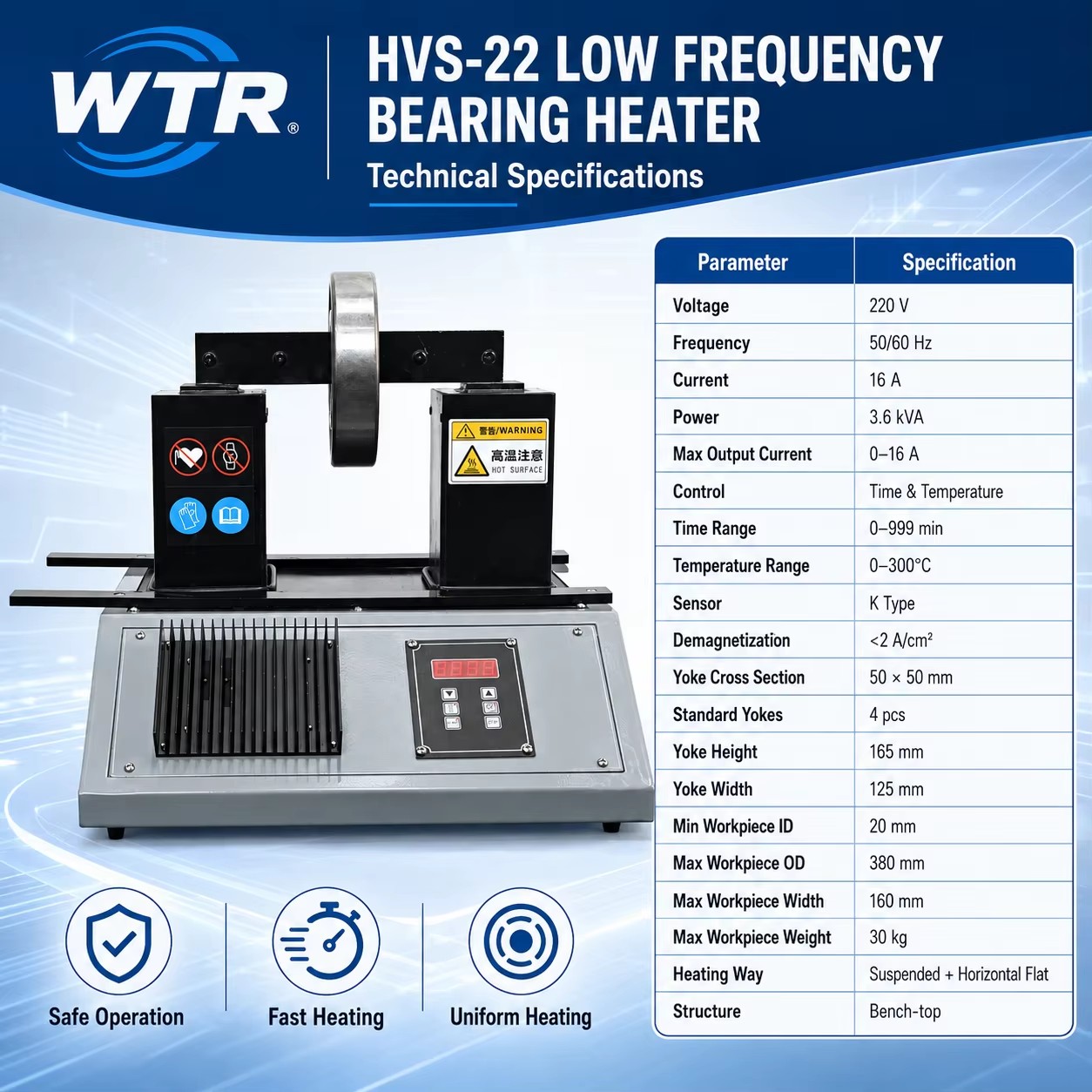
Efficient Industrial Heating Performance: The SIH series bearing induction heaters deliver reliable power from 2 to 8 KVA. They support both horizontal and vertical heating modes. These machines efficiently heat metal workpieces ranging from lightweight 12 kg bearings to heavy 100 kg components accelerating factory assembly operations and saving energy.
Precise Temperature And Time Control: Each unit features a clear digital display interface allowing operators to choose between temperature and time control modes. The system regulates heat up to 300 degrees Celsius and time up to 9999 seconds. An acoustic signal automatically alerts technicians when the cycle finishes ensuring workplace safety.
Wide Dimensional Range And Demagnetization: These heaters accommodate bearing inner diameters from 15 to 170 millimeters and outer diameters up to 530 millimeters. They process workpiece widths up to 200 millimeters. Automatic demagnetization activates after heating limiting residual magnetism to below 2 amperes per centimeter preventing metal dust adhesion.
Rugged Construction For Heavy Duty Use: Built with industrial grade materials the heaters feature a durable chassis weighing between 20 and 65 kg for maximum stability. This design is perfect for heavy machinery manufacturing and metallurgical plants. Using safe electromagnetic induction eliminates physical impact damage caused by traditional cold mounting.
Professional Accessories And Reliable Quality: Each heater provides quality equivalent to premium international brands. The package comes equipped with a sensitive magnetic temperature probe and specialized heating yokes to match varying inner diameters. Strict quality control before shipment guarantees long term stability for your assembly and maintenance teams.
Smart Energy Saving: Advanced induction technology provides rapid uniform heating for metal parts reducing power consumption and operating costs to deliver an eco friendly solution for factory maintenance
Frequently asked questions
To choose the right hydraulic puller, first measure the outside diameter of the part you are removing, such as a gear or bearing. Ensure the puller's maximum spread is at least equal to or slightly larger than this diameter. Next, determine the required reach based on how far the part is located on the shaft. For tonnage, a general rule is to calculate 7-10 tons per inch of shaft diameter. Choosing a slightly higher capacity prevents tool damage and ensures smooth, safe tool operations.
A 3-jaw configuration provides superior stability and distributes the pulling force evenly across the component, significantly reducing the risk of damaging the part or the shaft. It is the recommended setup for most standard applications. A 2-jaw setup is specifically designed for confined spaces where a 3-jaw configuration simply cannot fit. While a 2-jaw puller is highly versatile in tight areas, operators must be careful to align it perfectly to avoid slipping or off-center forces.
If the piston rod fails to retract, the return spring inside the cylinder might be broken, fatigued, or unhooked. Another common reason is excessive dirt, rust, or debris jamming the piston itself. Additionally, the release valve on the pump might not be fully opened, keeping hydraulic pressure trapped in the system. Ensure the release valve is turned completely counterclockwise. If the valve is open, disassemble the cylinder to clean the piston and inspect or replace the return spring.
After heavy operation, thoroughly clean the entire puller assembly, removing any grease, dirt, or metal shavings. Retract the piston completely to protect the polished rod from corrosion and physical damage. Inspect the jaws, linkage, and threads for any signs of cracking or excessive wear. Lightly lubricate all moving parts and pivot points with rust-preventative oil. Store the hydraulic puller and its accessories in a dry, clean case away from extreme temperatures and high humidity.
Jaw slipping is a major safety hazard, often caused by improper seating or severe misalignment. Ensure the pulling jaws squarely engage the back of the part, maximizing surface contact. Utilize safety straps, locking nuts, or a puller cage to physically bind the jaws together, preventing them from splaying outward under high tension. Furthermore, always start by applying light hydraulic pressure to verify the setup is perfectly centered and stable before applying maximum pulling force.
Generally, hydraulic pullers with self-contained hand pumps are designed to operate upright. However, they can often be used horizontally if the pump handle is positioned correctly so the internal pickup tube remains submerged in hydraulic fluid. Using them completely upside down will usually introduce air into the pump, causing it to lose pressure entirely. For tight, multi-directional applications, it is highly recommended to use a puller with a separate pump connected by a flexible hose.
The internal safety relief valve is a critical protective mechanism designed to prevent the hydraulic pump from exceeding its maximum rated pressure capacity. This prevents catastrophic equipment failure, such as burst cylinders or shattered puller jaws, which can cause severe injury. This valve is precisely calibrated at the factory and must never be tampered with or adjusted by the user. If your application requires greater pulling force, you must upgrade to a higher-capacity puller model.
Pumping beyond the maximum stroke limit causes the piston rod to strike the mechanical stop ring with tremendous force. This extreme internal pressure can permanently damage the stop ring, warp the cylinder body, blow out the main hydraulic seals, or cause the tool to fail catastrophically under load. Most high-quality pullers feature a red warning line on the rod. Once this red indicator becomes visible, you must stop pumping immediately, relieve the pressure, and reset the pulling setup.