
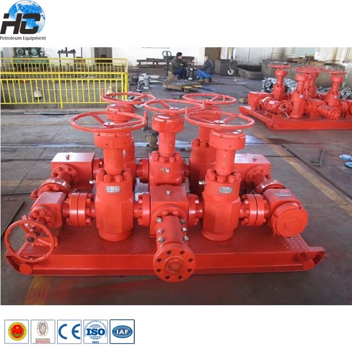
Well control system oil and gas manifold / choke manifold diagram for wellhead assembly
Choke manifold is a system of valves and chokes for controlling the flow from the well usually has two flow paths, one adjustable choke used primarily for cleaning the well up and facilities to install and change choke of fixed sizes for a more accurate flow control during main well flow periods.
Choke manifold is used during well testing,. The positive choke has a fixed diameter and the size of the orifice on the adjustable choke can be varied. In addition the adjustable choke allows fixed chokes to be switched out as needed without stopping the well, increasing the flexibility of the overall system.
The technical parameters about choke manifold
| Design Pressure | Size | Dimensions L X W X H | Configuration |
| psi | inch | inch | |
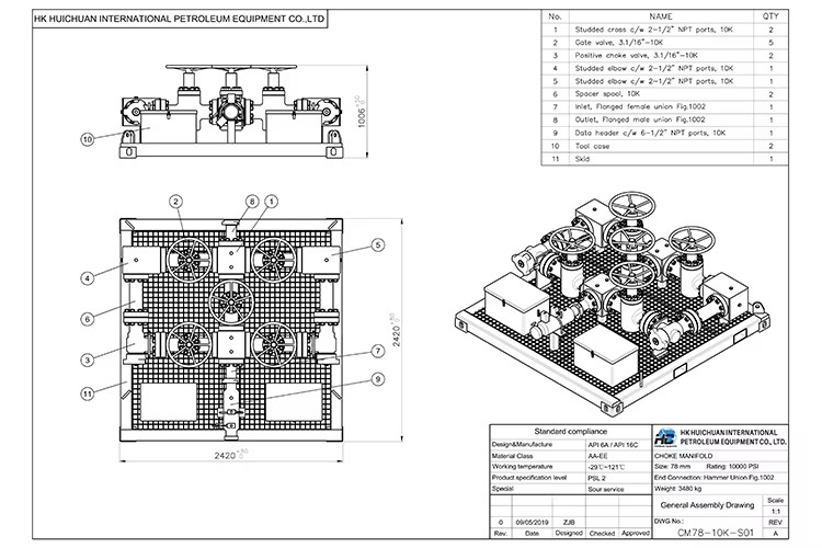
| 5000 | 3.1/16" | 90.9 x 89.6 x 32.5 | 5 x Manual Valves 1 x Adj.Choke & 1 x Pos. Choke 1 x Data-header |
| 5000 | 3.1/16" | 90.9 x 135.7 x 41.8 | 2 x Hyd.Valves & 6 x Man. Valves 1 x Adj.Choke & 1 x Pos. Choke 1 x Data-header |
| 5000 | 4.1/16" | 76 x 108.9 x 74.0 | 4 x Manual Valves 1 x Adj.Choke & 1 x Pos. Choke 2 x Data-header & 1 x Lifting Arm on Skid |
| 10000 | 3.1/16" | 99.9 x 95.6 x 39.4 | 5 x Manual Valves 1 x Adj.Choke & 1 x Pos. Choke 1 x Data-header |
| 10000 | 4.1/16" | 108 x 178.25 x 46.0 | 8 x Manual Valves 1 x Adj.Choke & 1 x Pos. Choke 1 x Data-header |
| 10000 | 4.1/16" | 85 x 120.0 x 85.0 | 4 x Manual Valves 1 x Adj.Choke & 1 x Pos. Choke 2 x Data-header & 1 x Lifting Arm on Skid |
| 15000 | 3.1/16" | 103.5 x 161.9 x 73.1 | 4 x Hyd.Valves & 4 x Man. Valves 1 x Hyd. Adj.Choke & 1 x Pos. Choke 1 x Data-header |
| 15000 | 4.1/16" | 103.5 x 161.9 x 43.63 | 8 x Manual Valves 1 x Adj.Choke & 1 x Pos. Choke 1 x Data-header |
| 15000 | 4.1/16" | 96 x 175.0 x 72.2 | 8 x Manual Valves 1 x Adj.Choke |
Technical drawing of choke manifold
Main features of oil and gas manifold / choke manifold diagram as below
ntrol the well fluid flow. 2.Built-in Cameron style gate valves which can be redressed on pipeline. 3.Standard two flow system: one through a positive choke and the other through an adjustable choke that can be converted into a positive choke. 4.Provides a means for fluid sampling, real-time pressure and temperature monitoring, and chemical injection. tal-to-metal, double seal to ensure reliability in harsh environments. 6.15000psi adjustable nozzle adopts gear handle,which can reduce the operating torque. 7.Positive choke is equipped with tungsten steel lining,making it twear-resisting and corrosion resistant.
Customers visit and the third party factory inspection are warm welcomed at any time.Strict quality control is our first promision to
Any question or interest about our choke manifold, please don't hesitate to contact with us. It's our honor to help and support your business.
Just send your inquiry in the textbox below!


-
Step 1
Payment and order readiness
Minimum order: 1 Units
Payment terms, specifications, and order details are confirmed before preparation begins.
-
Step 2
Preparation
30 days
-
Step 3
Packaging and dispatch
Packaging details are available on request.
Final packing, freight, and delivery dates are confirmed before dispatch.
Customer reviews
No reviews yet
Be the first customer to review this product.
Write a review
Request custom sourcing
Can’t find what you’re looking for? Share the requirement and our sourcing team will find the right industrial product.