Product description
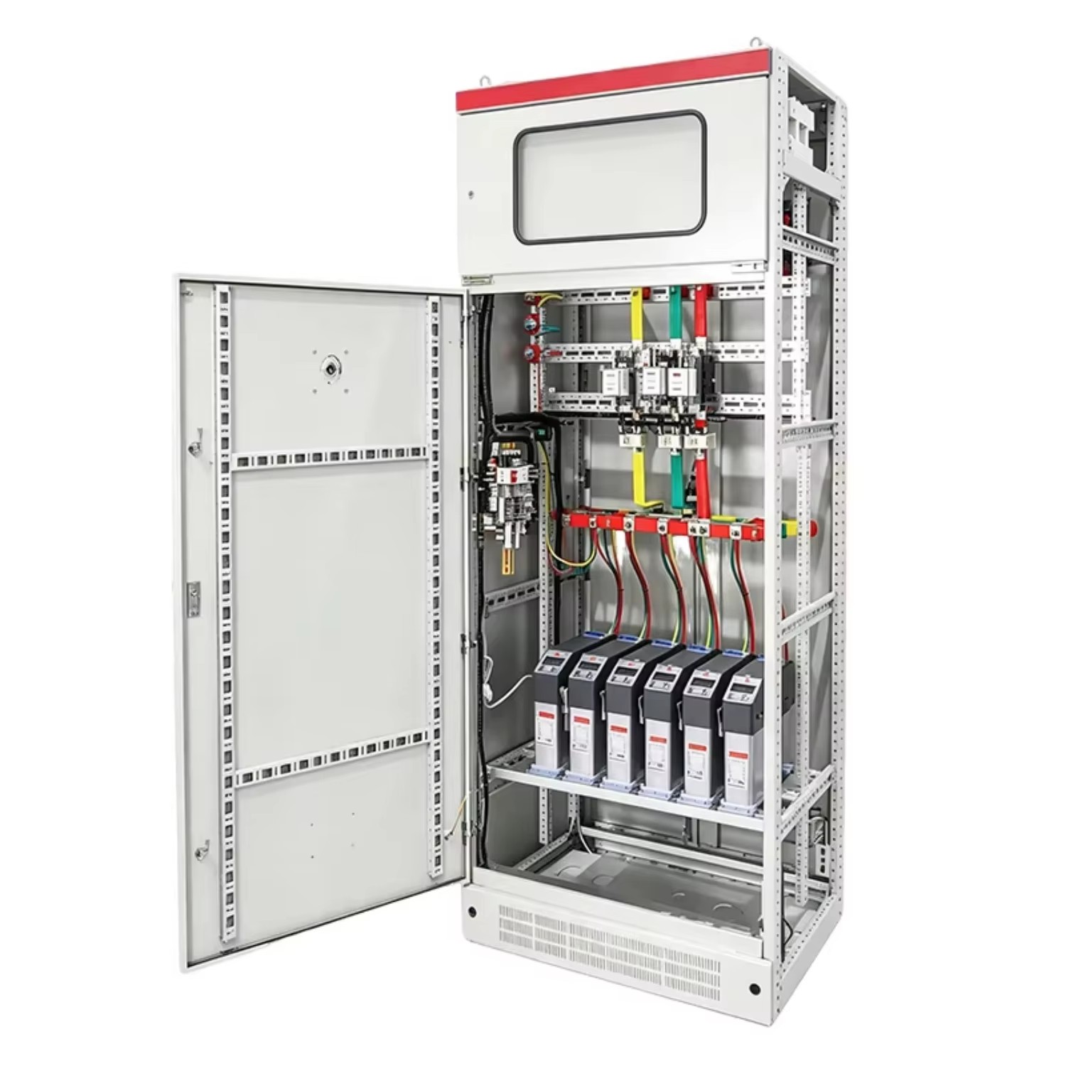
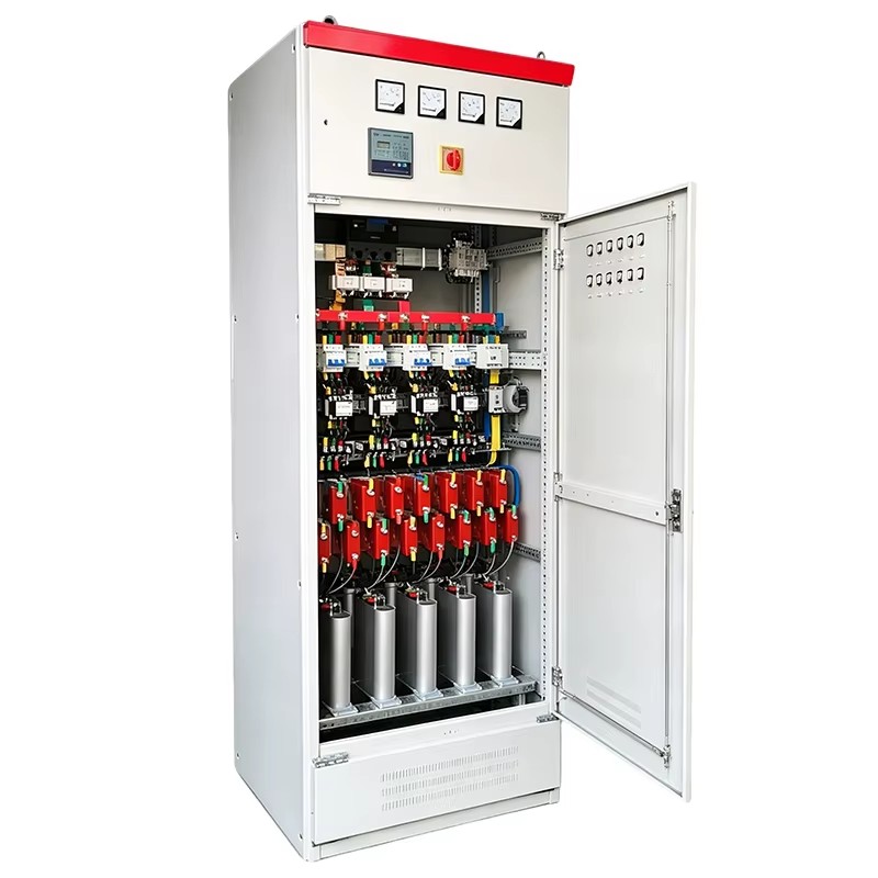
(1)Capacitor Bank arrangementThe capacitor equipment, unless being supplied in the LV distributionsection of a Package Substation, It is mounted in a free standing enclosure designed for indoor/outdoor use. Thescope of supply include, but not be to, the followinga) Capacitor units, comprising several capacitor elements connected in a three phase arrangement enclosed in aluminum case, with their terminals brought out.b) MCCBc) Switching devices to connect the capacitor sub-banks to the supply. The switching of the capacitors are in response to the changing reactive load.d) Reactive power regulator and controller and associated cabling.e) Protection equipment and all associated cabling.f) All CT’s required to implement the scheme.g) All primary and secondary cabling.(2)Capacitor ElementsThe capacitors elements are preferablybe wound from a metallized polypropylene film dielectric to produce a dry type(3)Capacitor UnitsThe single capacitor elements are assembled into delta connected groups of 3, as many groups of 3 capacitors being connected to achieve the required capacitance of the capacitor unit. The assemble group of capacitor elements are contained within aluminumcase with the terminals brought out through bushings. The bushings are of well processed porcelain or cast resin, approved for outdooruse at continuous voltage, and hermetically sealed to the aluminum case. The terminals are heavily tinned and suitable for standard copper conductors. All capacitor units are provided with an insulating terminal cover.The clearance between two capacitor units is not less than 5 cm.Discharge resistors are connected across the external terminals, which suitably rated to drain the residual voltage to 50 volts within 60 seconds after the capacitor is disconnected from the supply.(4)Moulded case circuit breakersIf a Moulded Case Circuit Breakers (MCCB) is used as the mains supply isolator to the capacitor bank then it’s circuit breaker mechanismsshall be of the tripfree pattern to prevent closing the breaker onto a faulty circuit, and engraved to indicate ‘ON/OFF’ position and rated current.The MCCB ensure protection against circuit overloads and against short circuits bymeans of electronic protection thermal and instantaneous magnetic trips. all MCCB can be adjustable to rated current of capacitor bank thermal protection adjustment range (0.5 ÷1 ) In magnetic protection adjustment range (2 ÷ ≥ 10) In.The MCCB have the feature to limit the fault current to the rating of the MCCB. for capacitor banks rated at 140 kvar the rated current for MCCB 400 A, ICU ≥45 KA. ICS ≥ 50% ICU for all MCCB.(5)AC Magnetic ContactorsContactors used for power factor correction including limiting resistor to avoid inrush currentContactors used for switching the capacitor sub-banks are designed to withstand the surge currents associated with capacitive ans provided to prevent manual operationof the contactor. Terminals and contacts are shrouded to prevent inadvertent finger contact.All switchgear and protective devices and their connections are capable of carrying continuously 1.5 times the rated capacity of the capacitor unit to which they are connected, inaccordance with IEC 831 section6.Operating voltage for coil of contactors 220 v ± 10%.(6) Reactive Power RegulatorThe capacitor banks are equipped with reactive power controller which will detect and measure the reactive power on the LV network and initiate a control unit to switch the appropriate number of capacitorsub banks in or out. There is a manual on/off push button provided which will take control of the sub bank to allow switching to be under operator control. Indication and push buttons for manual operationof each sub bank are provided.The controller select the sub bank to be switched in and means provided to vary the duty cycle to ensure a reasonable distributionof switching operations between different sub banks.The system is designed to minimize disturbance on the system and to avoid hunting. The controller is automatically switch off the capacitor bank in the event of loss of the 20 kV supply and be capable of restarting the capacitor bank automatically on restoration of the supply.v The regulator measures and display the following ( active,reactive power, current, voltage, harmonies, power factor, frequency, capacitive load, number of stage in service………..).v The regulator protects the capacitor bank if the harmonies is equal or more than ( 15 %).v The regulator selects the suitable capacitor unit to put it in service with regardingto ( work's hours and the required reactive power).v Operating voltage 380 V with suitable protection.v Regulator can be adjustment automatic and manual.v C/k automatic no need program.v Adjustment range (0.8….1 inductive, 0.9…..1 capacitive) acc. to IEC 61010-1.v Adjustment for time operation for range (5 …. ≥ 240 sec)v Regulator can put the stages in operationafter select the power factor( no need program)v Power consumption from voltage circuit ≤15 VA.v Starting current ≤ 20 mA(7)Capacitor Bank EnclosureEach enclosure is to be fully complete with front hinged and lockable access doors and have side mounted cable entry chamber for dry type cable entry from below.The enclosure is to comprise folded steel panels appropriately welded to ensure a rigid design. If the enclosure is constructed of panels bolted to a weled steel frame, the frame must be hot dip galvanized to ISO 1461 to ensure long maintenance free life.