DN100 Aluminium Double Flanged Pneumatic actuator powder butterfly valve
Advantages
• aims to provide
• Over 30 YEARS manufacturer of actuated valves, MASS CUSTOMIZATION acceptable.
• 3 production base, large stock, SHORT LEAD TIME, same day shipping.
• German imported manufacturing facilities, 100% Q.C passed before shipping, quality assured. Industrial standard 1 YEAR (12 months) warranty.
• ISO 9001 certificated, with extra certifications include CE, RoHS, SGS, BV, explosion & fire safe.
• OEM / ODM service available.
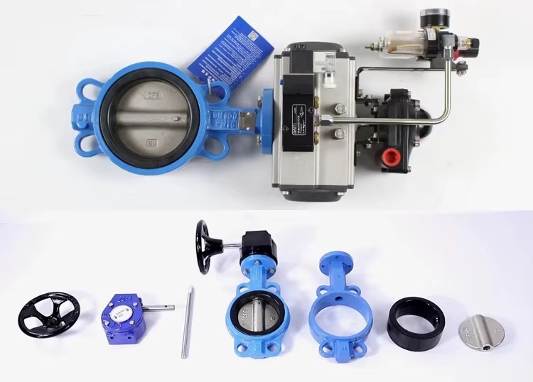
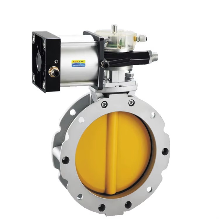
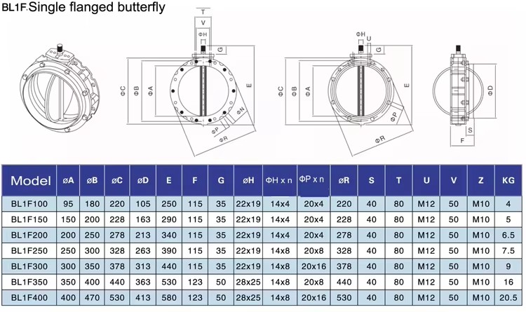
The Pneumatic powder butterfly valve is mainly used for the switch box, the material door and the silo with a powdery or granular boring. It can be applied to all powdery and granular materials, which can be installed under the material door, material box, silo, screw or other types of conveyor. Single flanged valves with top flange and dismantling parts. It is suitable for connecting flexible bushing, double flange valves, the same flange at the top and bottom, gravity casting body, higher strength than die casting valve body, high polymer material for rotary valve plate, wear resistance, less components, light weight and easy handling.
Features 1. Simple and compact construction, quick 90 degrees on-off operation. Mininmized operating torque, energy saving. 2. Bubbles-tight sealing with no leakage under the pressure test. 3. The connection of driven part conforms to ISO5211. 4. Wide selection of materials, applicable for various medium. 5. The valve body and disc are accurately machined which results in low operation torque and long service life and reliability. 6. Can be disassembled, material-specific recycling possible. n be installed at the end of pipe for lugged type butterfly valve.
Technical Parameters
| Size Range | 2"~12", DN50~300 |
| Acting Mode | Double Acting, Spring Return (Single Acting) |
| Operating Pressure | 1.6MPa |
| Air Supply Pressure | 2.5 to 8 bar |
| Lifespan | 1,000,000 (1 Million) Times |
| Angle of Rotation | 90° ±4° |
| Body Material | Cast iron, SS304, SS316, SS316L |
| Disc Material | Cast iron, Stainless Steel |
| Sealing Material | NBR, EPDM, VITON, PTFE |
| End Connection | Wafer, Flanged, Lug |
| Applicable Media | Control of Water, Air, Gas, Oil, Liquid, Steam |
| Optional Actuation | Handlever, Electric Actuated, or Pneumatic Actuated |
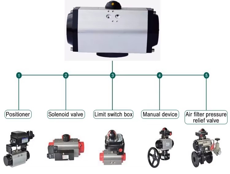
| Optional Accessories | Namur Solenoid Valve, Limit Switch, F.R.L, Position Indicator, Manual Device |
| Application | Food & Beverage, Water & Wastewater, Ultra Pure Water, Desalination, Chemical, Textile, Pharmaceutical, Pulp & Paper |
Design and Manufacturing Standards Design and Manufacture: GB/T12238-2008 Connection Standard: JB/T 79.1-1994 ASME B16.10 Structure Length: GB/T12221-2005 ASME B16.5 Pressure Testing: GB/T13927-2008
Pneumatic Actuator
Transmission structure principles
When the compressed air enters the pneumatic actuator through Nozzle A (as shown in Fig 1), the air will drive the double piston straightly moving toward two ends ( cylinder head end) and the piston rack will drive the gear of the rotary shaft by 90 degrees counter-clockwise. In this case, the valve will be opened. At this moment, the air in both ends of pneumatic actuator is discharged through Nozzle B. On the contrary, when the compressed air entered both ends of the pneumatic actuator through Nozzle B (as shown in Fig 1), the air will drive the double piston to straightly move towards the middle position and the piston rack will drive the gear of the rotary shaft by 90 degrees clockwise. In this case, the valve is closed. At this moment, the air in the middle of the pneumatic actuator is discharged through Nozzle A. What is aforementioned is the transmission principle. According to users' needs, the pneumatic actuatorcan be equipped with transmission principles contrary to the standard type. In other words, the valve will be opened when the rotary shaft rotates clockwise, while the valve is closed when it rotates counterclockwise. Single acting (spring return type) pneumatic actuation is implemented along the Nozzle A which is the air inlet, while Nozzle B is the air outlet (a muffler shall be installed in the Nozzle B). When Nozzle A inlets air, the valve will be opened, while the valve will be closed by the spring force when the air source is cut off.
Certifications & compliance
CE
Complies with EU standards


 France
·
France
·