Methane Gas Generation Plant CO2 CH4 Capture Biogas Liquefication Equipment Amine Adsorption Methane Gas Purifier
Exhaust gas emitted by industrial equipment such as fertilizer plants, refineries, coal/gas-fired power plants, cement plants, fermentation plants, and ore processing plants is the main source of carbon dioxide (CO2).
CO2 Recovery Plant - Gas Sources & Applications
| Gas Source | Gas Application |
| Alcohol plant fermentation gas | Food-grade CO2 for beverages, dry ice production |
| Sugar plant fermentation gas | Carbonation in soft drinks, pH control in water treatment |
| Synthesis ammonia (fertilizer) plant | Urea fertilizer production, enhanced oil recovery (EOR) |
| Methanol plant | Methanol synthesis feedstock, industrial cooling |
| Refineries | Petrochemical feedstock, carbon capture & storage (CCS) |
| Chemical plants | Neutralization agents, fire suppression systems |
| CO2 mine | Medical-grade CO2, welding shielding gas |
Main technology of CO2 capture, liquefaction and purification: Carbon dioxide capture refers to the process of using physical absorption, chemical absorption, pressure swing adsorption (PSA) and other technical means to treat tail gas with a CO2 concentration between 10% and 50% to reach or exceed 95%, and then finally purify it to the required industrial and food grade through processes such as desulfurization, adsorption, drying, and liquefaction.
Solution A: Chemical Absorption Process
1. Pretreatment Stage
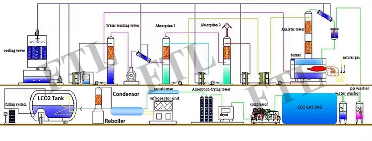
The CO2 gas first enters a water scrubber tower, where it thoroughly contacts circulating cooling water through a spray system. During this process, the gas temperature is reduced from an initial 120-180°C to an optimal treatment range of 40-60°C, while effectively removing over 90% of SO2 and more than 95% of dust particles. The scrubbing water maintains optimal washing efficiency through a pH automatic adjustment system, with treated wastewater being recycled after sedimentation and filtration.
2. Absorption Stage
The cooled CO2 enters a packed absorption tower, where it countercurrently contacts a 30%-35% concentration MEA solvent sprayed from top to bottom. At operating temperatures of 25-35°C, selective absorption reactions occur, increasing the CO2 concentration in the flue gas from 10-15% to a rich solution loading of 0.4-0.6 mol CO2/mol MEA. The absorption efficiency reaches 85%-92%, with exhaust gas CO2 content reduced to below 2%.
3. Regeneration Stage
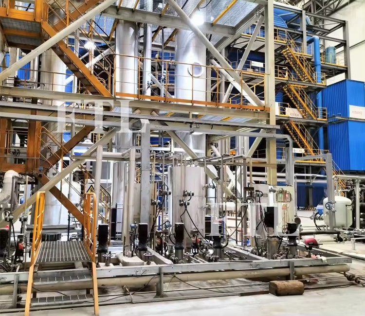
The CO2-rich solution is preheated to 70-80°C via lean-rich heat exchange before entering the regeneration tower. Using 0.12-0.15MPa steam for indirect heating, desorption is completed at a precisely controlled temperature of 92±2°C. The regeneration tower features a three-stage condensation system, ensuring the outlet CO2 gas maintains <100ppm water content and 99.5%-99.8% purity. The regenerated lean solution is cooled to 40°C before returning to the absorption tower, with solvent consumption maintained below 0.5kg/t CO2.
4. Buffer Storage
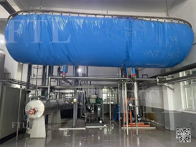
The air bag unit is mainly set between the water scrubber and the CO2 compressor. Its function is to compensate for the change in the amount of CO2 produced by the fermentation tank, act as a buffer, and stabilize the suction pressure of the compressor. Through the suspension method, the proximity switch is controlled through the PLC to ensure the smooth automatic operation of the compressor.
5. Compression Process
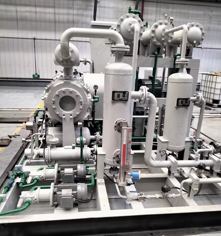
A two-stage oil-free piston compressor first pressurizes the gas to 0.6-0.8MPa, followed by intercooling to below 45°C, then second-stage compression to 1.8-2.2MPa with outlet temperatures <90°C. Each stage includes cyclone separators + precision filters for oil/particulate removal, with automatic drainage systems discharging 5-10L condensate hourly.
6. Purification & Drying
Compressed CO2 first passes through parallel activated carbon adsorption towers, with >15s contact time removing 99% H2S and organic sulfur. Subsequent molecular sieve drying towers reduce the gas dew point from ambient to below -60°C at 2.0MPa. The dual-tower configuration enables 8-hour continuous operation with 4-hour thermal regeneration cycles.
7. Liquefaction & Purification
Refrigerant transcritical refrigeration system liquefies CO2 at -25~-30°C and 1.8-2.0MPa. The 15° inclined condenser with automatic vent valves discharges 0.5-1.5% non-condensable gases hourly, achieving 85%-90% liquefaction efficiency and final product purity of 99.9%-99.95%.
8. Storage tank
This unit primarily consists of a CO2 storage tank and associated valves. the tank is made of 16MnDR Cryogenic stainless steel. The liquefied CO2 from the condensation process flows into the storage tank for preservation. To facilitate monitoring of the liquid CO2 level, the tank is equipped with level gauges that enable real-time observation of the CO2 liquid level. These gauges also function to control the upper limit of the liquid level and automatically trigger alarm signals when necessary.
9.Electrical Control Unit
The system utilizes a Programmable Logic Controller integrated with an industrial computer for operation, ensuring user-friendly and intuitive control. All operational statuses of the equipment are displayed graphically or through English menus, providing clear visibility of automatic/manual operation interfaces and historical fault records. Closed-loop control is implemented for all critical points, enabling the system to perform self-diagnosis of faults.
Solution B: Pressure swing absorption (PSA)
Pressure swing absorption (PSA) achieves separation based on the differences in adsorption capacity or adsorption rate of different gases at different pressures. There are two main approaches to PSA: high-pressure adsorption with reduced-pressure desorption, and atmospheric-pressure adsorption with vacuum desorption.
CO2 adsorption separation uses a solid adsorbent to selectively adsorb CO2 from a mixed gas. The CO2 is then desorbed under certain regeneration conditions to achieve CO2 concentration. Generally speaking, the stronger the adsorbent's binding force with CO2, the greater the CO2 adsorption capacity and the better the selectivity, which is more beneficial to the adsorption process. However, this also means a more difficult desorption process and higher regeneration energy consumption. Furthermore, due to its slow temperature regulation, industrial-scale CO2 adsorption separation processes are primarily based on PSA.
Application: Exhaust gas with CO2 content >30%
We also have some other processing technology such as Membrane separation, cryogenic distillation, Catalytic combustion, etc, we will make the professional solution based on customers' detail requirement
Our Strict testing and manufacturing standard